
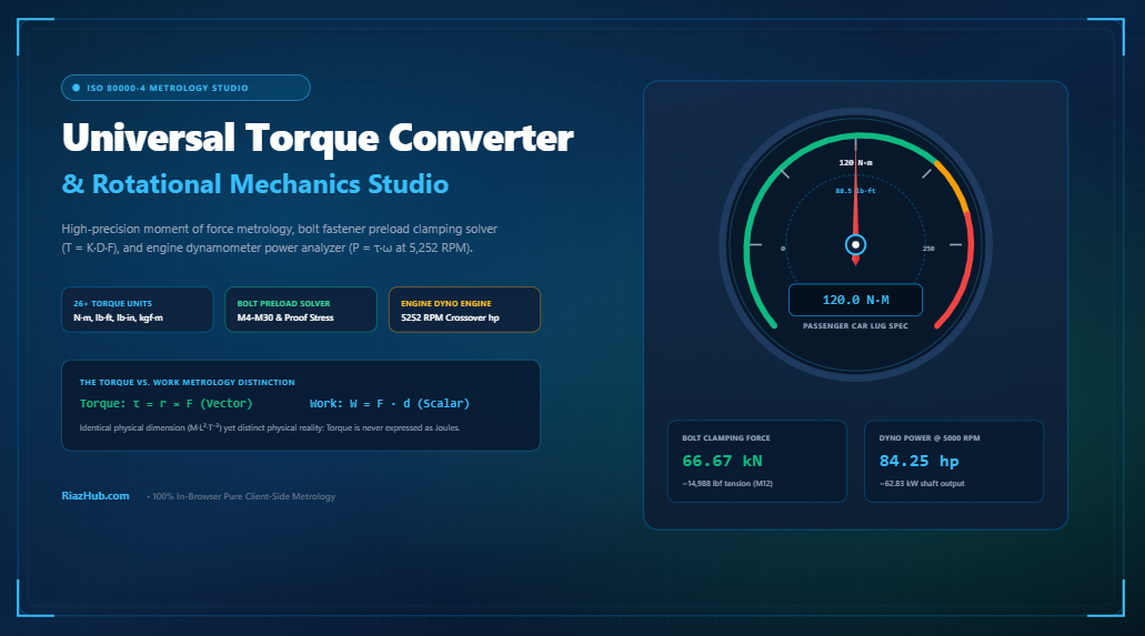
The Engineering Metrology of Rotational Mechanics: Torque, Bolt Clamping Physics & Dynamometer Dynamics
1. The Fundamental Role of Torque in Mechanical Engineering
In mechanical engineering, automotive powertrain design, and structural assembly, few physical quantities are as ubiquitous and as frequently misunderstood as torque (also referred to as the moment of a force). Whether torquing cylinder head studs to exact stretch specifications, calibrating an eddy-current engine dynamometer, or tuning an industrial robotic servo, accurate torsional measurement is paramount to mechanical integrity.
When assembling high-stress mechanical systems, engineers cannot afford guesswork. To instantly translate values across global engineering standards, engineers use the Universal Torque Converter & Fastener Tension Studio on RiazHub, an in-browser metrology engine that computes moments across 26+ units with zero server round-trips.
2. BIPM SI Base Unit Definition & ISO 80000-4 Standards
Under the International System of Units (SI) governed by the Bureau International des Poids et Mesures (BIPM) and formalized in ISO 80000-4 (Quantities and Units — Mechanics), the coherent unit of torque is the Newton-meter (N·m).
1 N·m = 1 N × 1 m = (1 kg·m/s²) × 1 m = 1 kg·m²/s²
Base Dimensions: [M] · [L]² · [T]⁻²
One Newton-meter represents the moment resulting from a force of exactly one Newton acting perpendicular to a moment arm of one meter from the rotational axis. Calibration of mechanical torque measuring instruments adheres strictly to DIN 51309 and ISO 6789, which specify calibration classes from dial wrenches (typically ±4% accuracy) to high-precision laboratory strain-gauge transducers (±0.25% to ±1% accuracy).
3. The Torque vs. Work Clarifier: Why 1 N·m Is Structurally Distinct from 1 Joule
A persistent point of confusion among students and technicians is why torque is never stated in Joules (J), despite sharing identical dimensional units of mass × length² × time⁻² (kg·m²/s²). The answer lies in vector mathematics and physical definition:
⚠️ Vector Cross Product vs. Scalar Dot Product
Torque (τ) is an axial vector (pseudovector) resulting from the cross product of the position vector (lever arm r) and the force vector (F):
τ = r × F = |r| |F| sin(θ) n̂
Torque represents a rotational tendency. Crucially, zero movement is required. When you apply 120 N·m of torque to a frozen lug nut that does not move, torque is active, but the mechanical work performed is strictly zero!
Work (W) and energy are scalars resulting from the dot product of force and displacement vectors:
W = F · d = |F| |d| cos(θ)
Work requires displacement in the direction of the applied force. Under ISO 80000-4 and NIST SP 811 guidelines, expressing torque in Joules is a severe metrological violation.
To prevent documentation errors and mechanical misinterpretations, the interactive rotational torque studio includes an educational Torque vs. Work clarifier HUD that details these vector mechanics.
4. Pound-Foot (lb·ft) vs. Foot-Pound (ft·lb): The Engineering Convention
In the US Customary and Imperial engineering systems, you will often hear automotive mechanics say “foot-pounds” when referring to torque wrenches. However, professional engineering bodies including the Society of Automotive Engineers (SAE J1349) and the American Society of Mechanical Engineers (ASME) maintain a rigorous distinction:
- Pound-Foot (lb·ft / ft·lbf): Designated strictly as the unit of torque (rotational moment), where the pound-force acts perpendicular to a lever arm measured in feet. Exactly 1 lb·ft equals 12 pound-inches (lb·in).
- Foot-Pound (ft·lb): Reserved by standard convention for mechanical work and kinetic energy (the Imperial analog of the Joule).
Under the 1959 International Yard and Pound Agreement:
1 N·m = 0.737562149277 lb·ft = 8.8507457913 lb·in
5. Fastener Bolt Clamping Force & Preload Tension Physics
Threaded fasteners are essentially precision mechanical springs. When you tighten a bolt, you stretch its shank along its longitudinal axis. This elastic elongation generates an axial clamping force (preload, Fp) that clamps joint interfaces together, preventing fatigue failure, joint separation, and fluid leaks.
The Short-Form Fastener Formula (T = K · D · F)
In industrial fastener engineering, the relationship between applied torque and developed clamping tension is modeled via the standard short-form formula:
T = K · D · F_p ⇔ F_p = T / (K · D)
Where:
• T = Tightening torque applied to fastener (N·m)
• K = Nut factor / friction coefficient (dimensionless)
• D = Nominal bolt diameter (meters)
• F_p = Resulting axial clamping force / preload (Newtons)
Where Does the Applied Torque Actually Go?
A common misconception among mechanics is that tightening torque directly translates into clamping force. In reality, up to 90% of the torque applied by your wrench is completely wasted overcoming friction:
- ~50% Under-Head Bearing Friction: Consumed by the bolt head or nut underside spinning against the washer or flange face.
- ~40% Thread Flank Friction: Consumed by the helical mating threads rubbing against each other under increasing contact pressure.
- Only ~10% Axial Tension: Converted into useful elastic stretch and clamping preload force!
💡 The Tremendous Impact of the Friction Factor (K)
Because friction absorbs ~90% of torque, altering thread lubrication drastically impacts clamping preload. Applying 100 N·m on a dry zinc-plated M12 bolt (K ≈ 0.20) yields approximately 41.7 kN of clamping force. Applying that identical 100 N·m with moly or PTFE anti-seize paste (K ≈ 0.10) yields 83.3 kN doubling the tension and risking bolt yield failure!
You can simulate thread friction changes and evaluate fastener yield stress using the calculate bolt preload clamping forces tool, which supports metric bolts (M4 through M30), UNC fasteners, and strength classes from ISO 8.8 to 12.9.
6. Rotational Dynamometer Dynamics & The 5,252 RPM Crossover Law
In automotive powertrain testing, an engine dynamometer does not directly measure horsepower. A dynamometer measures torque using a load cell on a stationary lever arm, while a magnetic optical sensor tracks rotational speed (RPM). Horsepower is calculated mathematically from those two variables.
Power (Watts) = τ (N·m) × ω (rad/s) = τ × (2π · RPM / 60)
Mechanical Horsepower (hp) = (Torque in lb·ft × RPM) / 5252.113
Power (kW) = Power (Watts) / 1000
Notice the constant 5,252 in the Imperial horsepower formula. Where does it originate?
- James Watt defined one mechanical horsepower as 33,000 foot-pounds of work per minute (33,000 ft·lbf/min).
- One shaft revolution covers 2π radians:
33,000 / (2π) = 33,000 / 6.2831853 = 5,252.113.
Consequently, on any chassis or engine dyno graph displaying torque in pound-feet and power in horsepower on identical scales, the torque and horsepower curves will always cross at exactly 5,252 RPM! Below 5,252 RPM, torque is numerically greater than horsepower; above 5,252 RPM, horsepower is numerically greater than torque.
You can verify your engine’s power curve with the live engine dynamometer horsepower solver, which features dynamic RPM steppers and real-time kW/hp conversions.
7. Real-World Torque Spectrum: From Micro-Mechanics to Megawatts
To build intuitive physical appreciation for torsional moments, consider the vast span of real-world torque milestones:
| Mechanical Benchmark | Torque (N·m) | Torque (lb·ft) | Engineering Application |
|---|---|---|---|
| Wristwatch Winding Crown | 0.005 N·m | 0.0037 lb·ft | Horological mainspring gear trains |
| Smartphone Precision Screwdriver | 0.30 N·m | 0.22 lb·ft | Micro-fastening on delicate PCB boards |
| Human Wrist Twist (Bottle Cap) | 1.50 N·m | 1.11 lb·ft | Adult manual ergonomics limit |
| Automotive Spark Plug | 25.0 N·m | 18.4 lb·ft | Aluminum cylinder head threaded insertion |
| Passenger Car Wheel Lug Nut | 120.0 N·m | 88.5 lb·ft | 5-bolt alloy wheel clamp specification |
| Performance Twin-Turbo V8 Engine | 650.0 N·m | 479.4 lb·ft | Crankshaft output of sports sedans |
| Commercial Semi-Truck Diesel | 2,500 N·m | 1,844 lb·ft | 15-Liter heavy interstate freight hauler |
| Offshore Wind Turbine Main Shaft | 1,500,000 N·m | 1,106,340 lb·ft | Megawatt rotor hub driving main planetary gearbox |
8. Multi-System Torque Conversion Factors
When cross-referencing European ISO engineering drawings with North American SAE documentation, keep this exact conversion table handy:
| Unit Name | Symbol | Multiplication Factor to N·m | Measurement Family |
|---|---|---|---|
| Newton-meter (Base SI) | N·m | 1.0 (Exact) | SI Metric & Moments |
| Kilonewton-meter | kN·m | 1,000.0 | SI Metric & Moments |
| Newton-centimeter | N·cm | 0.01 | SI Metric & Moments |
| Pound-foot | lb·ft | 1.3558179483314 | Imperial & US Customary |
| Pound-inch | lb·in | 0.1129848290276 | Imperial & US Customary |
| Ounce-inch | oz·in | 0.0070615518142 | Imperial & US Customary |
| Kilogram-force meter | kgf·m / kp·m | 9.80665 | Gravitational Metric |
| Tonne-force meter | tf·m | 9,806.65 | Gravitational Metric |
| Dyne-centimeter | dyn·cm | 1.0 × 10⁻⁷ | CGS & Absolute |
9. Engineering Best Practices Summary
- Always calibrate wrenches: Check mechanical click-type and beam torque wrenches annually under ISO 6789 standards to guarantee ±4% calibration limits.
- Account for thread conditions: Never apply dry torque specifications to oiled or anti-seize coated fasteners without reducing wrench torque by the corresponding nut factor ratio (Kwet / Kdry).
- Differentiate lb·ft and ft·lb: Maintain professional mechanical drafting rigor by reserving lb·ft for torque and ft·lb for energy.
- Leverage automated solvers: Bookmark the Universal Torque Converter & Fastener Tension Studio on RiazHub for instant, accurate calculations across workshop, trackside, and engineering design tasks.
Universal Torque Converter & Mechanics Studio
High-precision torsional moments, fastener preload clamp forces (T = K · D · Fp), and dynamometer brake horsepower (P = τ · ω) computed 100% in-browser under ISO 80000-4 and SAE standards.
ISO 80000-4 & DIN 51309 Calibration
Under ISO 80000-4, the Newton-meter (N·m) is established as the primary unit for moment of force. Calibration of mechanical torque wrenches complies with ISO 6789 (Types I & II, classes A through G), typically guaranteeing ±4% accuracy for dial/click wrenches and ±1% for electronic transducers.
The Physics of Bolt Tightening (T = K · D · Fp)
In threaded fastener assemblies, approximately 50% of the torque applied is consumed by under-head bearing friction, 40% by thread flank friction, and only ~10% is converted into axial clamping force (Fp). Using thread lubricant (PTFE, anti-seize) drops K from 0.20 to 0.10, doubling clamping tension for the exact same wrench torque!
Pound-Foot (lb·ft) vs. Foot-Pound (ft·lb)
To avert confusion between torsional torque and kinetic work, mechanical engineering societies (SAE J1349, ASME) prescribe the pound-foot (lb·ft) for torque and reserve foot-pound (ft·lb) for energy. 1 lb·ft is defined as exactly 12 pound-inches (12 lb·in).
Zero-Leak Client-Side Metrology Privacy
This application executes 100% locally inside your web browser using HTML5 Canvas and native JavaScript double-precision floating math. No engine blueprints, bolt specs, or telemetry data are ever transmitted to any external server.